
Features
The MI family of telescope mounts includes the following major features:
- Distinctive conical geometry combining style, strength, and function
- A minimum of machined parts with no protruding motors or brackets
- Large drive gears on both axes with spring loaded worm assemblies
- Minimal visible hardware (i.e. nuts and bolts)
- Homing disk on each axis for remote operation
- Large shielded ball bearings supporting the telescope axes
- Sliding rocker-style base for latitude adjustment
- Slip clutches on both axes for easy setup
- Stainless steel counter-weights with threaded counter-weight shaft (German).
- Cover plates that shield the drive gears and servo motors
- A choice of computer controls – Servo II, AP GTO3, Bisque TCS
Polar Base
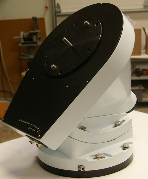
Each mount includes a polar cone fitted with a large upper bearing and a lower guide bearing. These pre-loaded bearings support the polar axis. The polar cone is attached to the rocker-base, which in turn is attached to the black anodized base plate. The base plate is bolted to the top of the observatory pier or column.
The contact area between polar cone and the rocker-base is concave-convex surface whose center is near the top face of the north bearing. As one slides the polar cone across the rocker-base, nearly full contact with the rocker-base is maintained. The center of mass of the polar assembly remains near the center line of the pier.
For polar alignment, each equatorial mount has adjustments for accurately aligning the polar axis to the celestial pole. Along the lower edge of the rocker-base are three large recessed setscrews. One setscrew is located at the back surface of rocker-base. Turning this setscrew slides the cone on the concave rocker-base increasing or decreasing the altitude of the mount. With this one setscrew, one can adjust the altitude of the mount to the required latitude of the observatory.
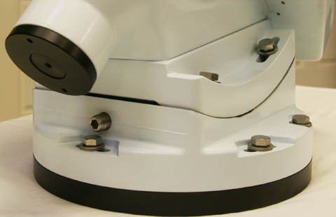
A pair of stainless steel setscrews on the east and west sides of the polar assembly allows one to rotate the entire mount on the base plate. With this pair of push-pull setscrews, one can adjust the azimuth of the mount as needed.
The mount should be installed on the observatory pier or column within a few degrees of true north (or south). Using the azimuth and altitude adjustments, one can get within a few arc minutes of the pole on the first night. For a permanently mounted mount, very precise polar alignment is an iterative process extending over several observing sessions.
The polar cone encases the right ascension axis, worm drive gea, and slip clutch. The drive gear and clutch are located near the top of the upper bearing. The slip clutch allows manual motion of the telescope for initial setup and for adjusting the telescope balance. When controlled by computer, the clutch is locked. This clutch design also provides a margin of safety in the event the telescope strikes the pier or other fixed object.
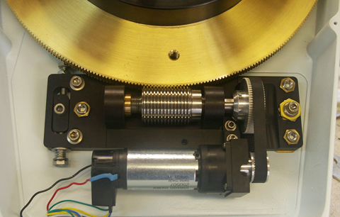
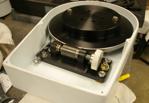
Each axis of the telescope has a large, fine pitch, worm gear with matching precision worm. Since the right ascension axis generally experiences more gear wear than the declination axis, for the RA axis we offer a solid bronze worm gear with stainless steel worm. On the declination axis we normally use an aluminum worm gear with a bronze worm.
The RA worm gear is paired with a precision worm that runs in class 7 ball bearings. The spring loaded worm bearing assembly allows fine adjustment of the worm to worm gear tension to minimize backlash in the gear train. The worm assembly and servo motors are inside a protective casing . No motors or brackets protrude from the mount.
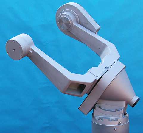
Fork Configuration
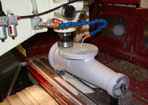
The equatorial fork configuration consists of a pair of tapered fork arms and a central hub. The thick-walled arms are cast of 356 heat trated aluminum using a hollow box design. Each fork arm is machined on computer controlled milling machines, assuring perpendicularity of the machined surfaces and uniformity in each set of fork arms. The declination axis of the assembled fork is perpendicular to the right ascension axis with an accuracy of 1 arc minute of angle or better.
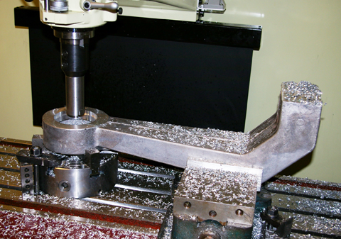
Since the arms are detachable from the fork hub, the fork arm separation can be machined to the customer's required dimensions by customizing the dimensions of the fork hub. The fork arms are bolted to the central hub using stainless steel hardware. Mechanical contact on the two bottom surfaces of each arm assures alignment and rigidity of the fork assembly. The central hub with the attached fork arms is bolted to the top face of the polar axis.
A pair of pre-loaded bearings in each arm supports each flange plate. The telescope tube attaches to the flange plate using dovetail plates. Interfacing a particular telescope tube to the fork requires customer-supplied dimensions, and in most case some custom machining will be required
One fork arm (usually the east arm) includes the declination gear housing with a fine pitch worm gear, a worm bearing housing, and a DC servomotor. A slip clutch allows one to balance the tube assembly and make fine adjustment whenever auxiliary equipment is added to the telescope tube assembly.
One fork arm holds the declination gear housing with a fine pitch worm gear, a worm bearing housing, and a DC servo motor. A slip clutch allows one to balance the tube assembly and make fine adjustment whenever auxiliary equipment is added to the telescope tube assembly.
Our fork mounts are available in several sizes. The compact MI-500F is suitable for payloads up to 120 pounds. This would includes telescopes such as Celestron 14 and Meade 14 Schmidet Cassedgrain telescopes, PlaneWave CDK12 and CDK14, and custom astrographs of 10 to 16 inch apearture.
The MI-750F is designed for payloads up to about 180 pounds. This would includes telescopes such as the PlaneWave CDK17 and CDK20, RC Optical 16 and 20 telescopes, Meade 16 Schmidt Cassedgrain telescopes, and custom imaging packages.
The MI-1000F is suitable for payloads up to about 300 pounds. This would includes telescopes such as the PlaneWave CDK24, and RC Optical 24 inch.
We also offer hybid fork model. This includes the MI500 polar base paired a MI-750 fork assembly. Using the larger fork assembly allows larger telescopes in the fork assembly, with restriction that the payload is 150 pound or less. A similar model is the MI-750 polar base with MI-1000 fork assembly.
Our largest fork mount is the MI-1000/1250. This features the MI-1000 polar base paired with our MI-1250 fork assembly. This mount is designed for telescopes such as the PlaneWave CDK24, and RC Optical 24-inch.
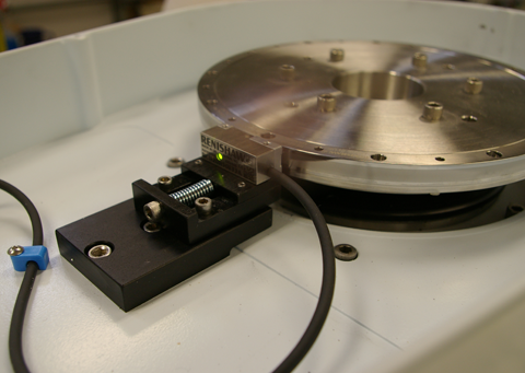
As an option, high resolution Renishaw encoders are now available for our fork mounts. Using the Servo II control, a precision encoder rings is installed inside the polar cone and on the fork arm opposite the declination drive. An readhead records the motion of the telescope with sub-arcsecond resolution. Independent of the drive gears and servo motor encoders, the tracking and pointing accuracy to the mount is enhanced using the Renishaw encoders. Tracking errors are reduced to a fraction of an arcsecond, and the pointing errors of the mount are measured in arc seconds over the entire sky.
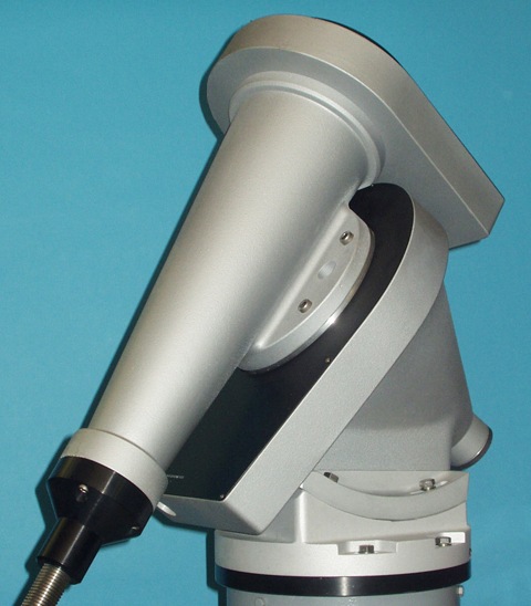
German Configuration
Our German equatorial mounts feature a conical declination assembly, which attaches to top face of the polar asembly. This casting is machined on special mandrels that assure near perfect alignment of the opposing bearing surfaces. The bottom surface of the declination assembly is machined perpendicular to the right ascension axis to an accuracy of 1 arc minute or better.
The tapered declination assembly features a large upper bearing and a smaller guide bearing at the opposite ends of the assembly. These pre-loaded bearings support the declination axis and the declination drive gear. The worm gear includes a slip clutch, allowing one to balance the tube assembly whenever auxiliary equipment is added to the telescope. A gear casing houses the drive gear, worm bearing housing, and DC servo motor. No motors or brackets protrude from the declination assembly.
As an option, high resolution Renishaw encoders are now available for our German mounts. Using the Servo II control, precision encoder rings are installed on the right ascension and declination axes. An electronic readhead records the motion of the telescope with sub-arcsecond resolution. Independent of the drive gears and servo motors, the tracking and pointing accuracy of the mount is determnined by the Renishaw encoders. Tracking errors are reduced to a fraction of an arcsecond, and the pointing accuracy of the mount is typically 5-10 arcseconds over the entire sky.
For the MI-500 and MI-750 mounts use a 2.0 inch diameter counter-weight shaft. Thisthreaded, stainless steel shaft attaches to a coupling at bottom of the declination assembly. The MI-100 uses a 2.5 inch threaded shaft. Depending ontelescope payload, the counter-weight shaft typically holds 80-250 pounds of counter-weights.
To atach the telescope of the mount, a telescope plate in bolted to the top surface of the declination axis. The telescope tube is attached to this plate using a dovetail plate or a custom instrument plate. We offer custom maching to connect a particular telescope tube to the mount based on the customer's requirements.
Our German mounts are available in three sizes. The compact MI-500G is suitable for payloads up to 220 pounds. This includes telescopes such as 7-inch to 10-inch refractors, 12 to 16-inch Newtonian telescopes, Celestron 14 and Meade 14 Schmidet Cassedgrain telescopes, PlaneWave CDK12 and CDK14, and custom astrographs of 10 to 16 inch apearture..
The versatile MI-750 is designed for payloads up to 300 pounds. This includes telescopes such as 8-inch to 12-inch refractors, large Newtonian telescopes, Meade 16 Schmidt Cassedgrain telescopes, PlaneWave CDK17 and CDK20, and RC Optical 16 and 20 telescopes.
The MI-1000G is suitable for payloads up to 500 pounds. This would includes telescopes such as 10-inch to 12-inch refractors, 20 to 24-inch Newtonian telescopes, PlaneWave CDK24, and RC Optical 24-inch.